Polski
 English
 Italiano
 Español
 Čeština
 Српски
 Deutsch
 Ελληνικά
 Slovenský

Each OLT purchased in our store at first is checked by the technical department. We check if GPON boards (GPBD, GPSD, GPFD), control boards (MCUD / MCUD1), GPON SFP module and the rest of the components - are in working order. The installed software is also verified and drivers needed for proper functioning. OLT terminals purchased from us are assembled and ready for using. In the video below, we want to show their structure, explain the use of individual boards and present the markings on the housing that facilitate correct assembly.
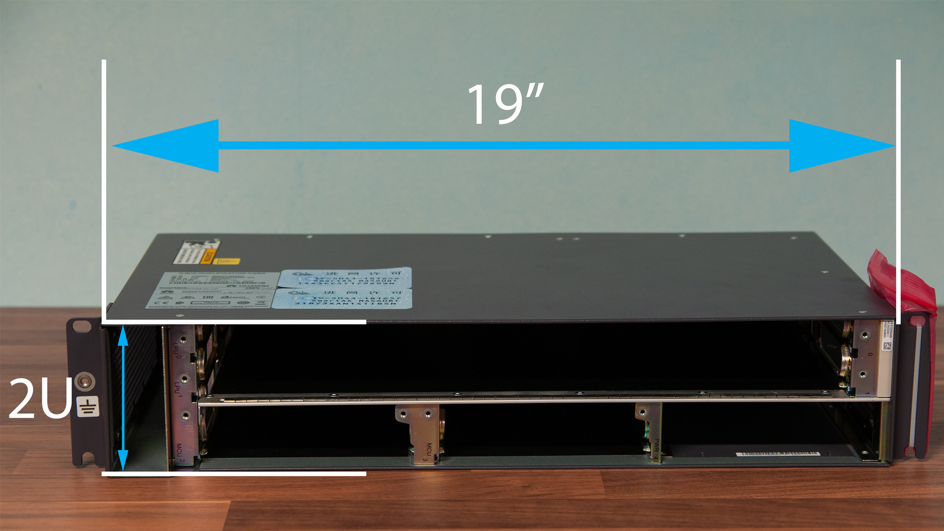
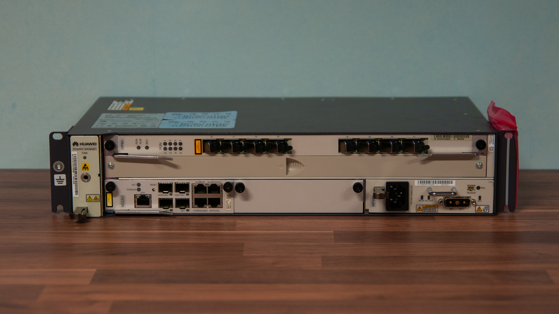
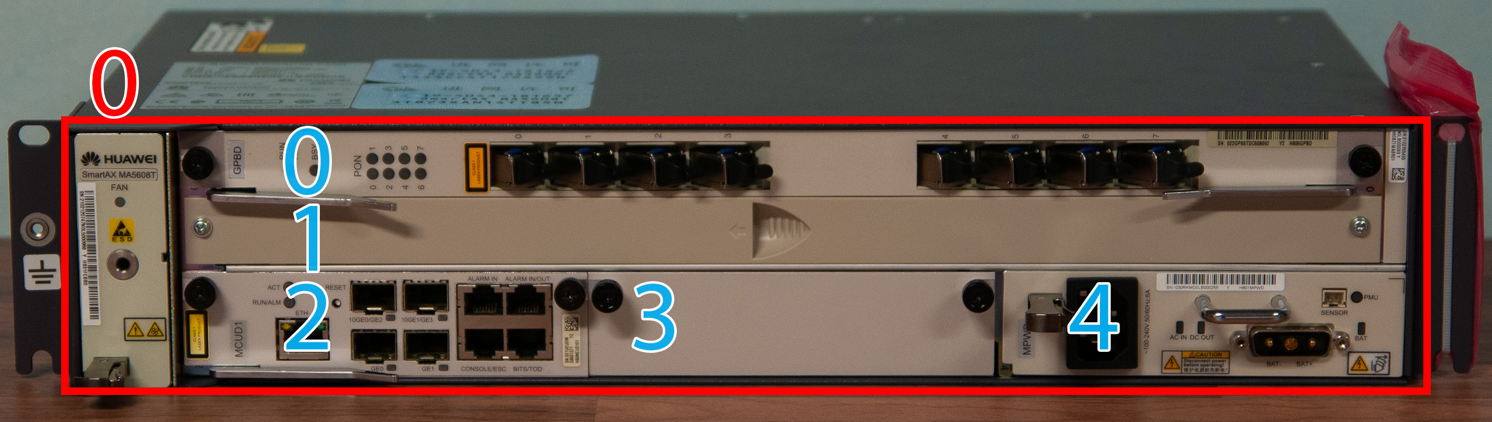
Let's start with the housing is adapted to the RACK 19" cabinet. This particular model occupies two slots (2U). Holds two interface boards two control boards, and one power board.(DC 48V lub AC 230V).
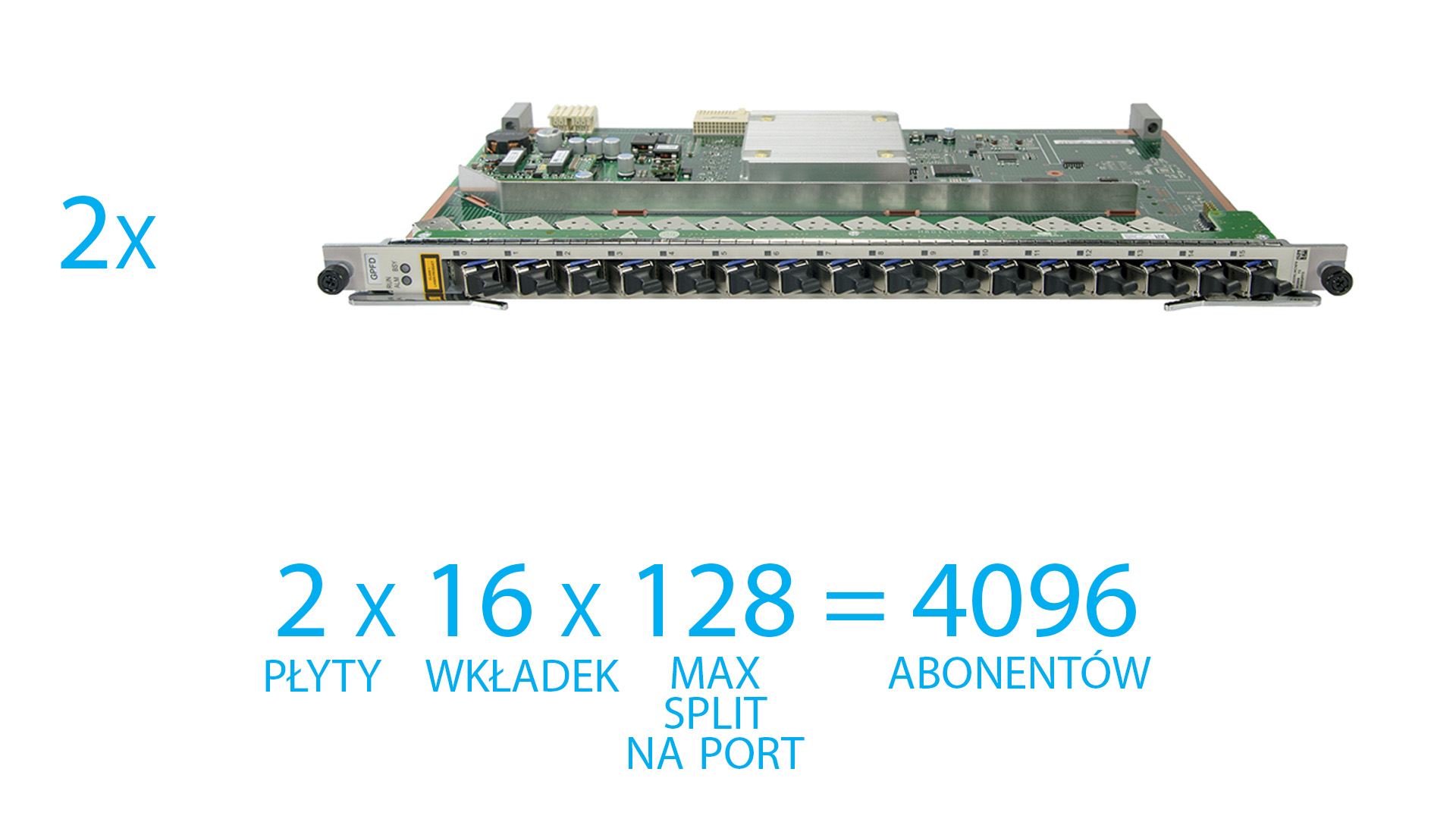
Using two 16-port GPON boards, theoretically, we can connect up to 4096 clients.
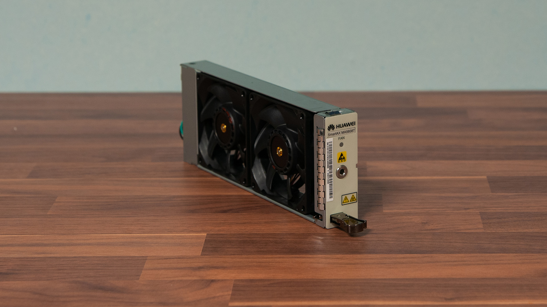
The first component is the fans without which the OLT system will start, but it won't allow GPON boards to turn on. Overheating can damage the device.
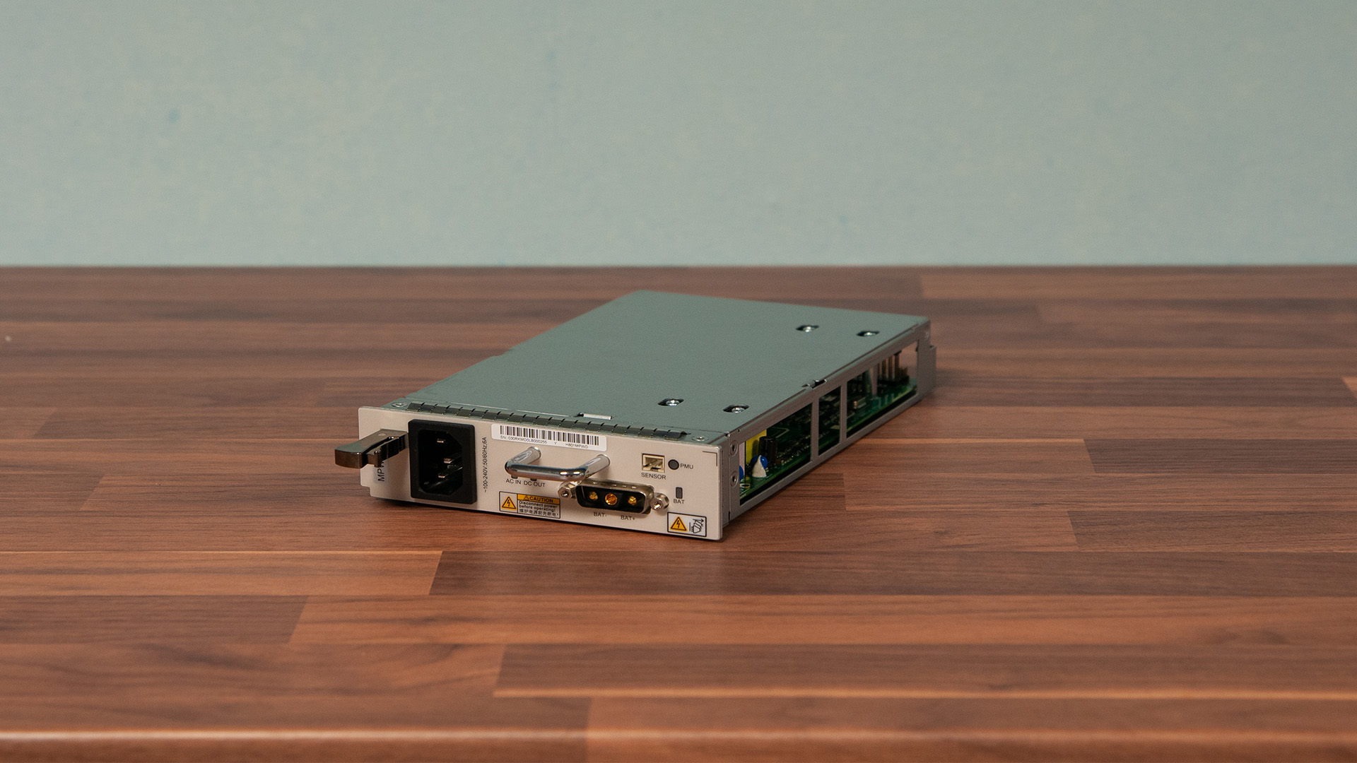
The second element is the power board. The MPWD model has the functionality of an embedded power system . We can connect four batteries to it and create a backup power supply. In the event of a power outage, customers will not lose access to the Internet and other services. In the presented set we have a model designed for 230 V AC power. A model designed to be powered from a 48 V telecommunications power system is also available.
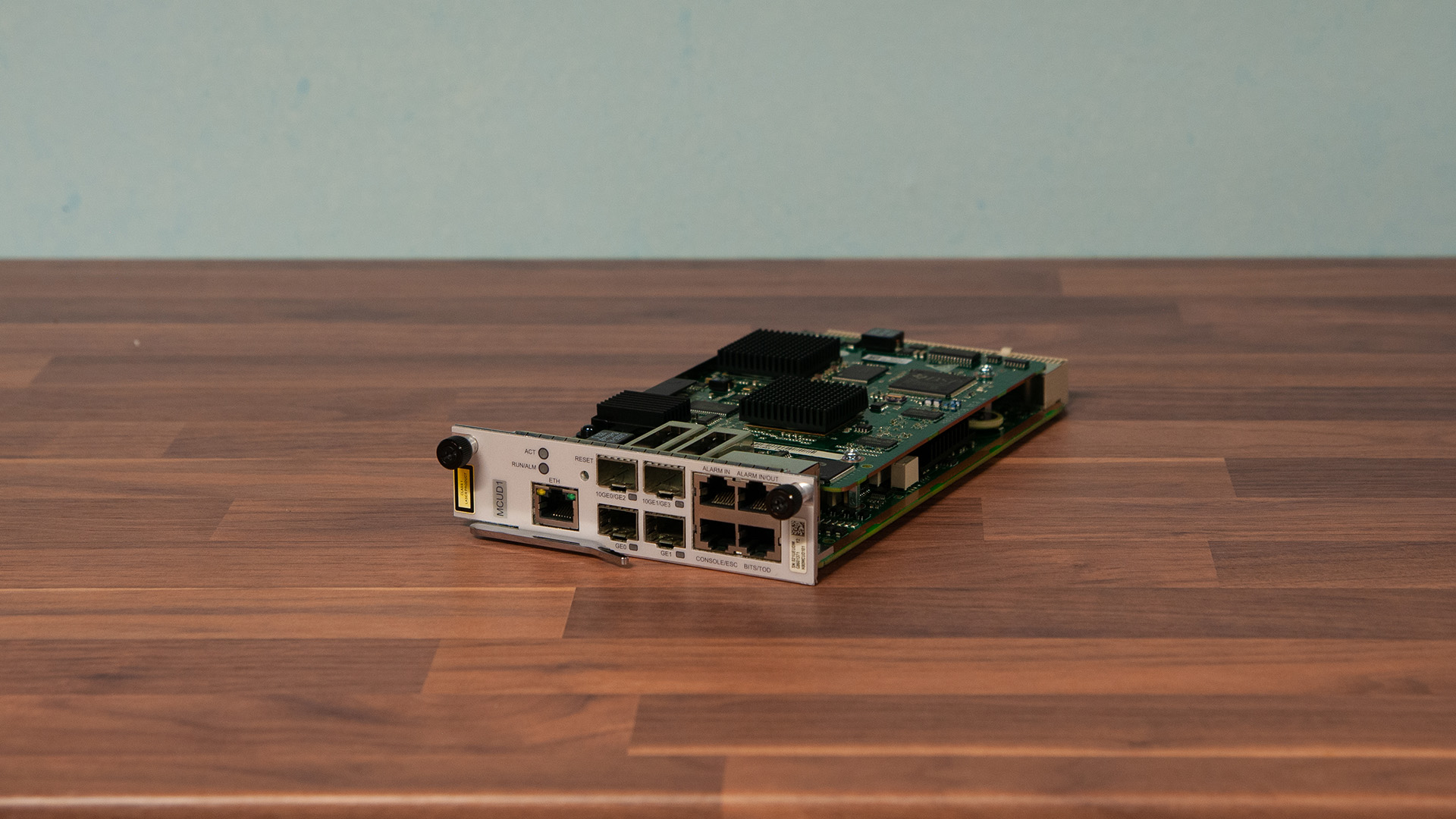
Then the main component of our device - Control board labeled MCUD or MCUD1. Our system is installed in it, it stores our configuration, through it we manage our OLT. In this OLT the control board also serves as an uplink board. The presented model has two SFP+ slots (10 Gb/s) and two SFP slots (1 Gb/s). The control card slot is labeled MCU. We put it in like the other boards, with the difference, at first we have to release the lock by pulling the lever.
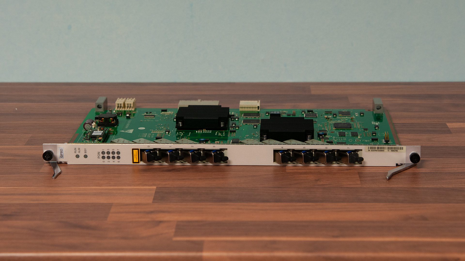
Now it's time for a interface board, GPON or EPON board. Through it, the OLT communicates with the ONT or ONU (receiving devices). The presented model has eight PON ports, with eight C + class GPON SFP module. There are three standards for GPON SFP module. B+, C+ and C++. The differ in the power range with which they transmit the fiber-optic signal. The assembly is similar to that of the control board.
| Type | B+ | C+ | C++ |
|---|---|---|---|
| Wavelength | Tx: 1490 nm Rx: 1310 nm | ||
| Port rate | Tx: 2,448 Gb/s Rx: 1,244 Gb/s | ||
| Optical power range | 1,5 - 5 dBm | 3 - 7 dBm | 6 - 10 dBm |
| Maximum receiver sensitivity | -28 dBm | -32 dBm | -35 dBm |
After assembly, put the covers in the empty places and tighten all the screws.
Everything is ready, so we power it. Depending on the number of components, starting OLT and full synchronization of components can take up to an hour. Access to configuration, we should get after a few minutes.
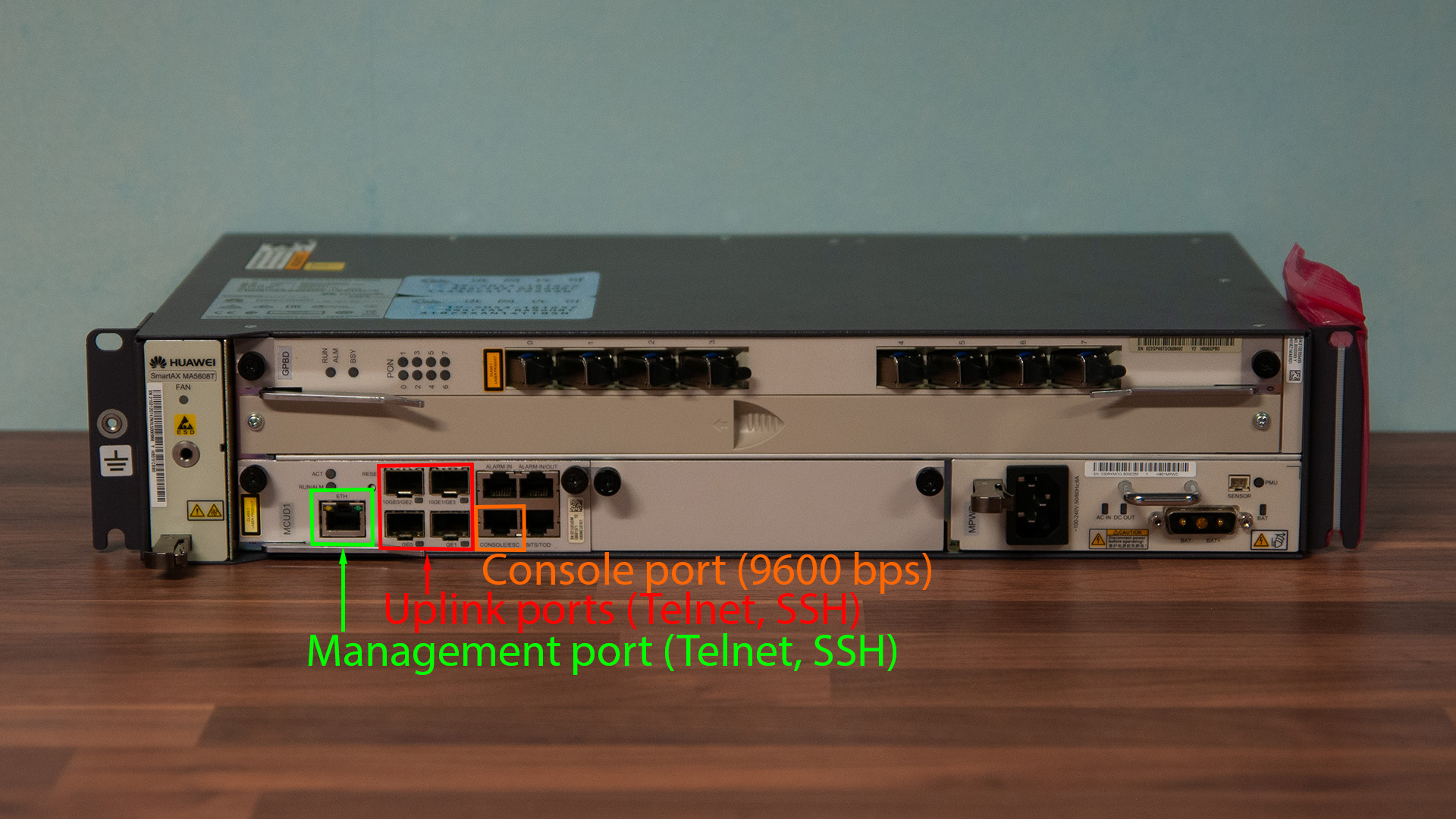
OLT configuration can be done via the console port (the bit rate is 9600), Telnet and SSH. Via the management port and uplink ports.
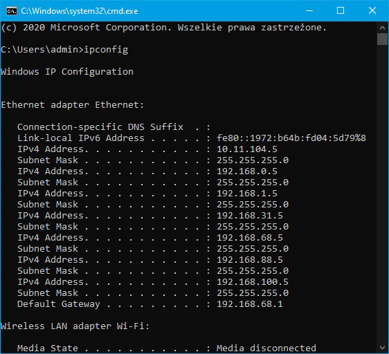
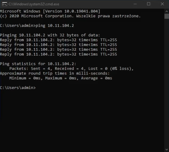
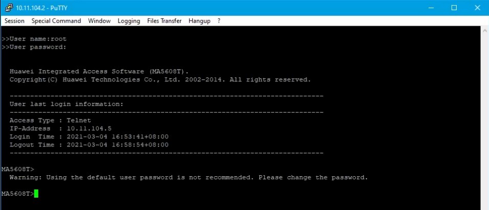
Our test device has been running for a few minutes, I connect the ETH cable to the management port, the other end is connected into a switch next to the computer. Default IP address of our OLT: 10.11.104.2 On the computer, we set an address from the same subnet to be able to log in. Ping the OLT - responding to ping.
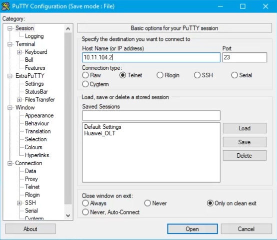
Turn on any program that supports Telnet connections, I will use Putty. I am putting the OLT IP address. I choose the Telnet connection protocol and click connect.
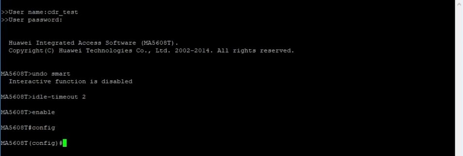
A terminal window was displayed and asking for login credentials. The default login is: "root" and the password is: "admin" lub, from software version R016, login is: "root" and password: "admin123"
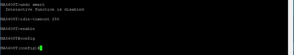
After successfully logging in, I recommend that you enter two additional commands. The first is: "undo smart", which turns off extra prompts and acknowledgments when typing commands, and "idle-timeout 255", which sets the idle timeout (logout) time to 255 minutes. Enter the command: enable increasing permissions, then: config to enter configuration mode.
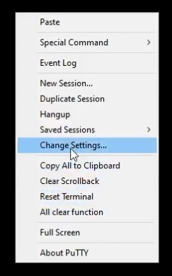
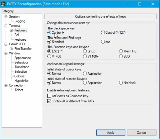
An additional tip in Putty program is a reconfiguration of the keys for deleting characters. By default, it is Shift + Backspace instead of Backspace. This can be change easily. While holding down the Ctrl button, click the right mouse button on the terminal window. Next Change settings and go to the tab Terminal -> Keyboard. I set the Backspace key to Control - H and I apply by clicking Apply button
Command “display board 0” shows us a list of the components mounted in the housing, except fans. 0 is the housing number. On the photo below I present the way of marking the boards. Comparing to what appeared in the terminal.
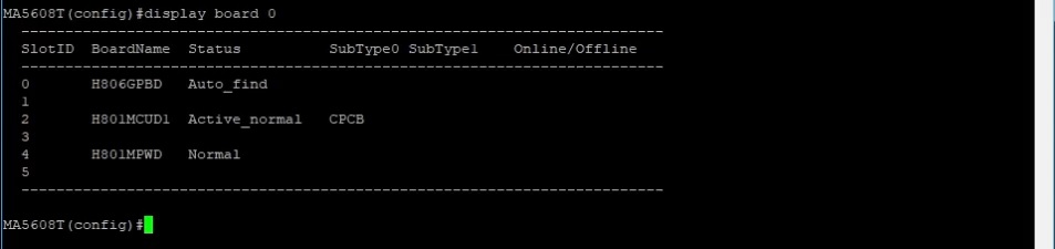
Boards can have several statuses: active_normal and standby normal, These two are reserved for control boards only, if we have two boards, one of them will be active and the other will be backup. Normal - everything is fine, failed - we have a problem with the board: it may be that the software driver is missing, or has been damaged in some way. config - the board is synchronizing. Sometimes control board during synchronizing may assume the status for a while Standby_failed. The last status is Auto_find - newly inserted board has been detected and is waiting for add.
| Component | Status | Meaning |
|---|---|---|
| Control board | Active_normal | Working, active board |
| Standby_normal | Backup board will switch to active get damage | |
| Standby_failed | The board is damaged / sometimes the board may take this status for a while during synchronization | |
| All | Config | The Board is synchronizing |
| Everything except the control board | Normal | Everything is fine |
| Failed | The board is damaged or the driver for it is missing in the software | |
| Autofind | The board has been discovered and is pending confirm |
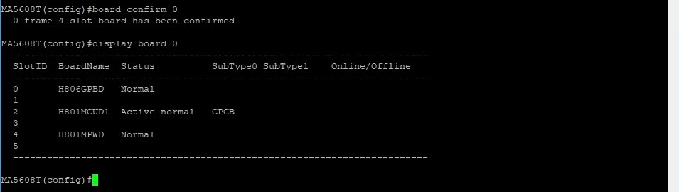
We confirming the boards with the command "board confirm 0" After a while, we check the status of the boards again. Our board, which previously had a status Auto_find now it has status Normal.
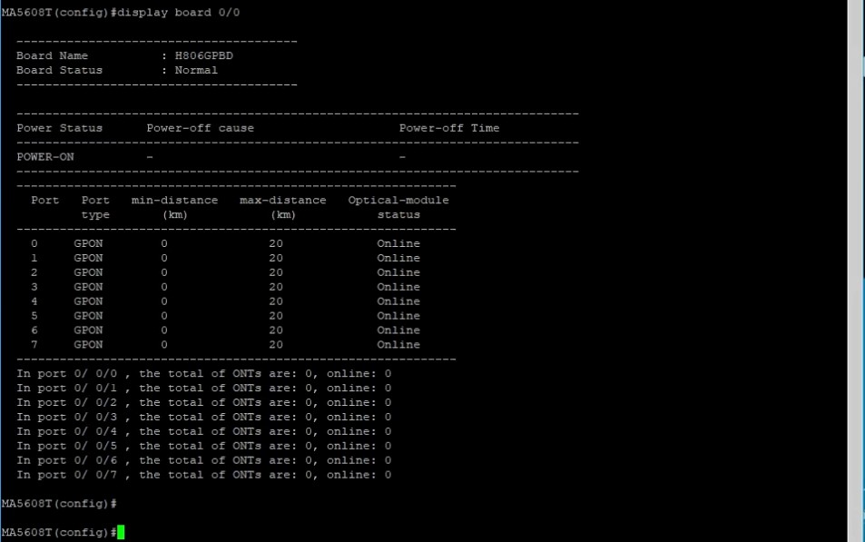
"display board 0/board number" It shows us more details about a board, eg are the SFP module working properly.
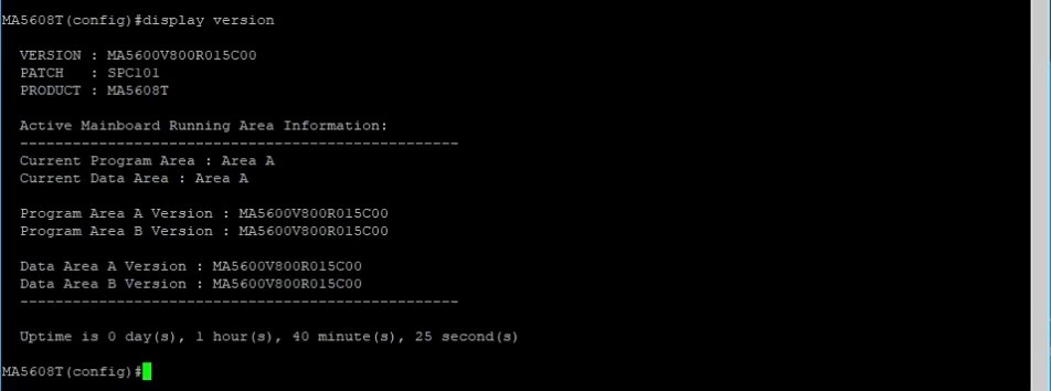
Command “display version” display the active and standby software version. If we have two control boards
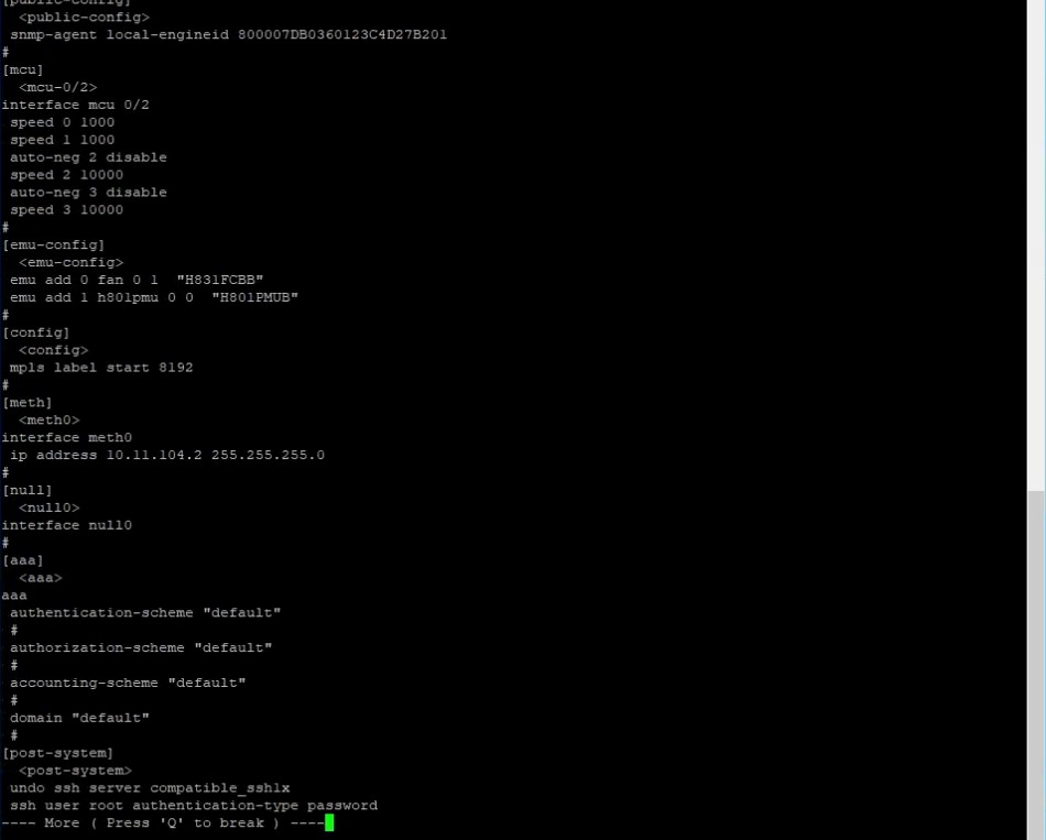
"display current-configuration" - displays the current configuration of the device.
If we don't know the full command software can help us by typing ? in the terminal. The software will show us the available options. When typing the command, we can click tab key and the terminal will add the final part.
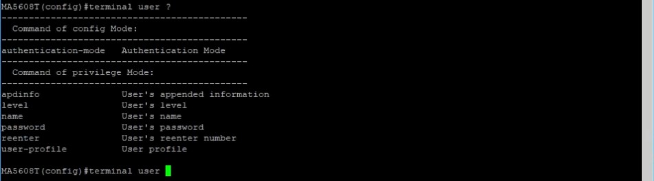
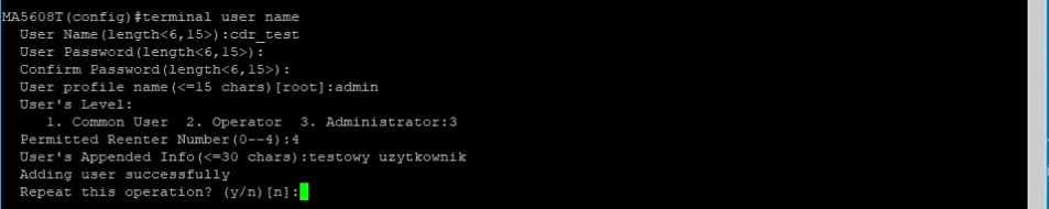
"terminal user name" - creating a new user with login, password, confirmation password, profile name, permissions, number of login attempts, account description, and the question if we want to add another user
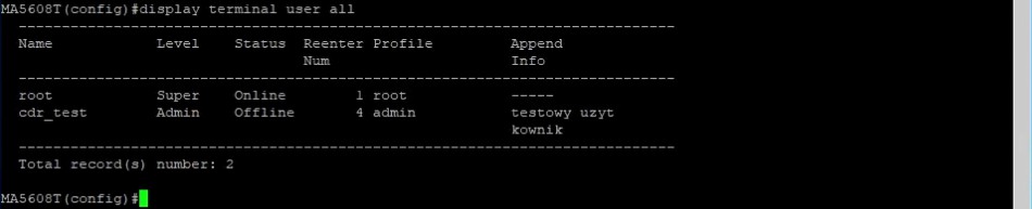
"display terminal user all" - show us the accounts of all users.
"interface meth 0" - enter to managing management port
"ip address 192.168 68.6 24" - set ip address

The port IP address changed, so we lost connection. So we have to log into the device using the new IP address, If we set at the first login "idle-timeout 255" and we try to log in to the root account again, that we will receive a message that root is still logged in.
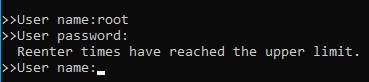
For this we have created an additional account to be able to log in. Alternative solution to this problem is set shorter logout time for example, for two minutes
We will add now VLAN 20 on the uplink port
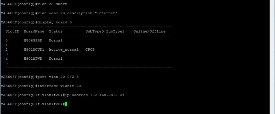
"vlan 20 smart" - create VLAN 20
"vlan desc 20 description „LAN_INTERNET”" - create VLAN description, I will use it as the source of the Internet.
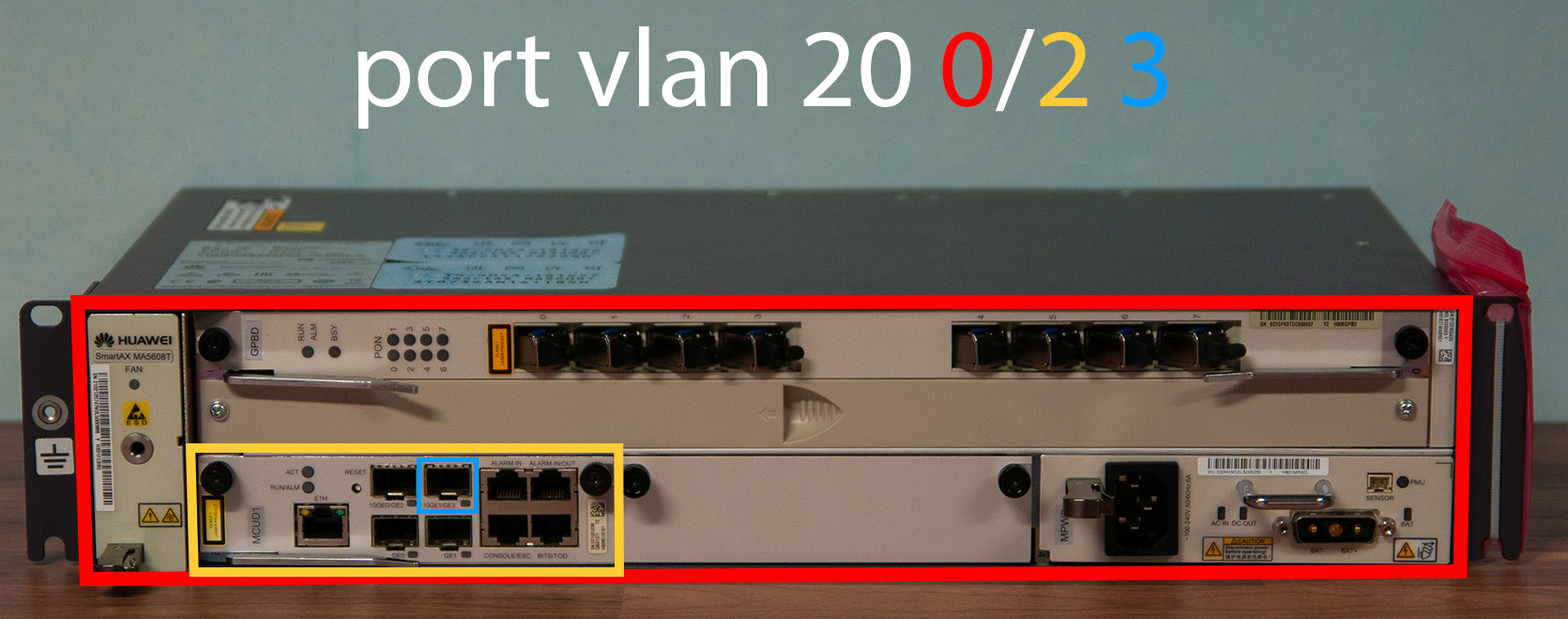
"port vlan 20 0/2 0" - Assigning a vlan to a specific port.
"interface vlanif 20" - enter to vlan management
"ip address 192.168.1.18 24" - set IP address
"quit" - quit from vlan management
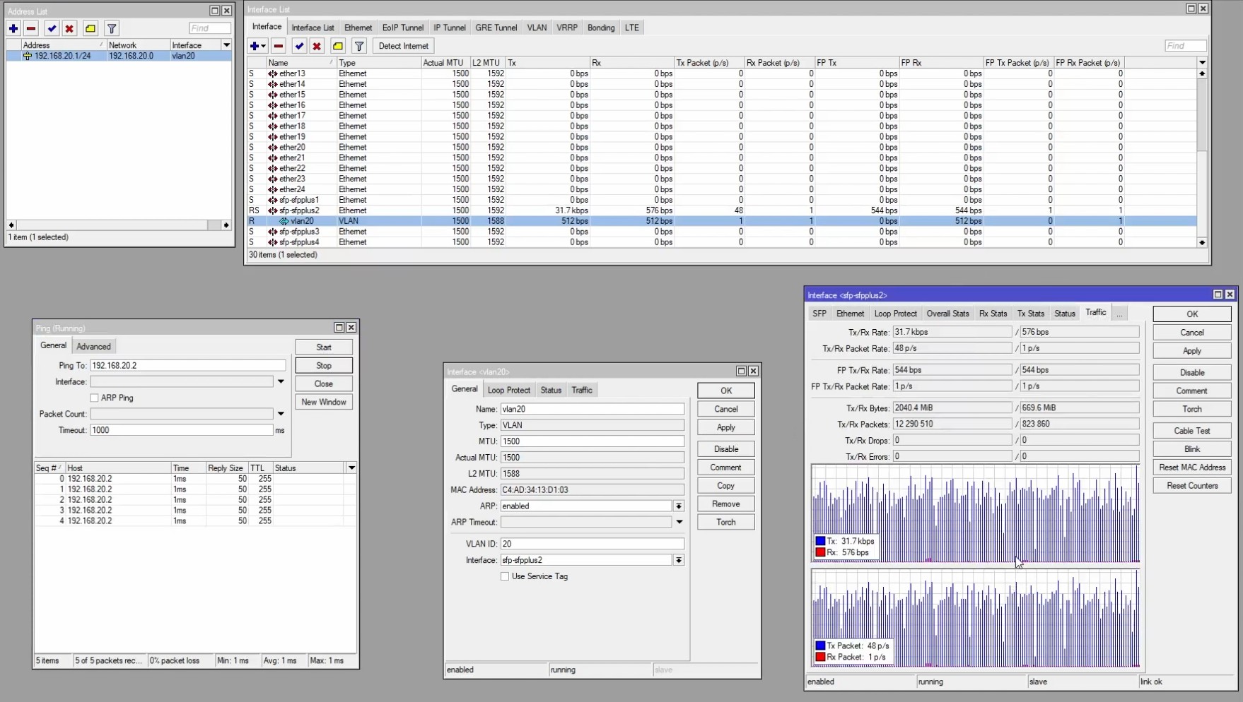
Let's ping OLT from the Mikrotik side via VLAN 20, as we can see, everything works.
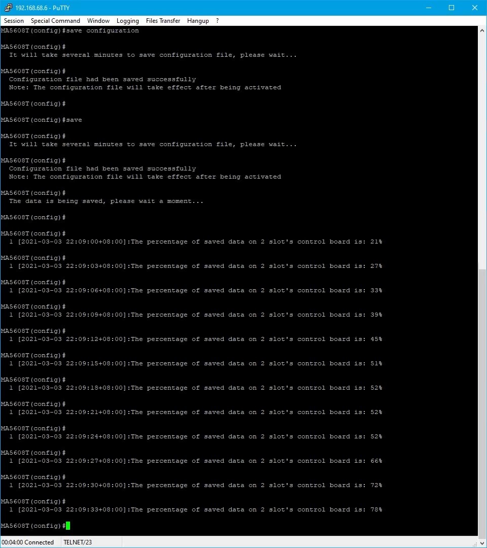
save the configuration with the "save configuration" command and then "save". The first prepare a configuration file, the 2nd writes it to the board or two control boards.
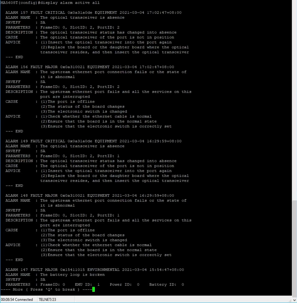
"display alarm all" - displaying all alarm messages on our device.
Hope each of you has access to your device now and understands the steps we made through first launch. I encourage you to leave a subscription and Like on our Fanpage, so that you will not miss any innovations and newly published videos on the channel. If you have any problems, please contact our technical support department. Contact