-
$
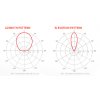
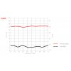
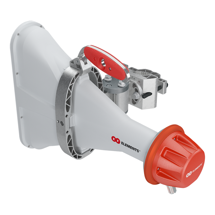
The radiation pattern of 60° Asymmetrical Horn CC Antenna is 60° wide in the azimuth plane and 25° in elevation. Increased gain and excellent beam efficiency greatly improve coverage planning options. 60° Asymmetrical Horn CC Antenna exceeds the traditional patch array sector antennas thanks to the high stability of the radiation pattern throughout the bandwidth of operation. Outstanding noise rejection and precision of the radiation pattern favor the antenna for high-densityaccess point clusters and densely co-located sites. 60°
AsymmetricalHorn CC features a pair of N-female connectors ensuring a wide range of radio connectivity.
Game Changing Sector Antennas
Asymmetrical Horn CC Antennas provide unique asymmetrical beam shape while maintaining excellent noise rejection and overall excellent performance of a well designed horn antenna with N-female connectors. Enabling new levels of network scalability and throughput increase. Asymmetrical Horn CC antennas complement the successful Symmetrical Horn Antennas.

Unique Asymmetrical Beam
Asymmetrical Horn CC Antennas have unique beam shape. The beam cross-section in bore sight is elliptical: wide in azimuth and narrow in the elevation plane. This is useful for deployments where asymmetrical beam shape delivers better coverage.
No Side Lobes
Asymmetrical Horn CC Antennas have naturally suppressed side lobes because of their optimized design: they focus energy into a single main beam. Absence of side lobes enables excellent noise immunity of a network when using Asymmetrical Horn CC Antennas.
Wide Band Performance
The radiation pattern of Asymmetrical Horn CC Antennas is stable over the whole band width of operation.
Balanced H + V Beams
Asymmetrical Horn CC Antennas have balanced Horizontal and Vertical beam patterns. Balanced H+V beams are very difficult to achieve for antenna with asymmetrical beam shape and this is the area where all competitive products on the market fail. Balanced H+V beams are critical feature for stable link performance when switching channels.
Gain Performance
Asymmetrical Horn CC Antennas have higher gain compared to Symmetrical Horn Antennas with the same azimuth beam width. Asymmetrical Horn CC Antennas cover ultra-wide frequency range: 5180-6000 MHz with excellent VSWR performance.

Perfect Coverage Pattern
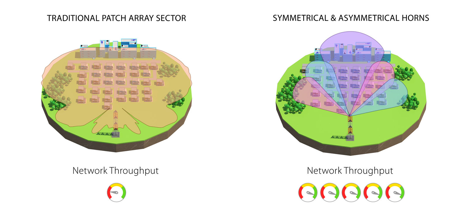
Mainstream patch array sector antennas have radiation pattern extremely wide in the azimuth and extremely narrow in the elevation plane. If an AP is deployed on a tall tower, customers near the tower suffer from low AP signal level. Asymmetrical Horn CC Antennas provide valuable extra degrees of the elevation beam width, shrinking the null zone while preserving the increased gain for long-range performance.
Breakthrough Scalability: Expanded
RF elements® Horn CC Antennas enable extraordinary network scalability. Asymmetrical Horn CC Antennas are a new addition to the toolbox of a modern WISP. Unique beam performance, precise radiation patterns, and increased gain push system scalability even further.
N-type Connectors
Asymmetrical Horn CC Antennas feature N-female connectors, used with a wide range of radios, such as MimosaTM A5c, Cambium NetworksTM PMP 450, LigoWaveTM, and many others.

Built Like a Tank
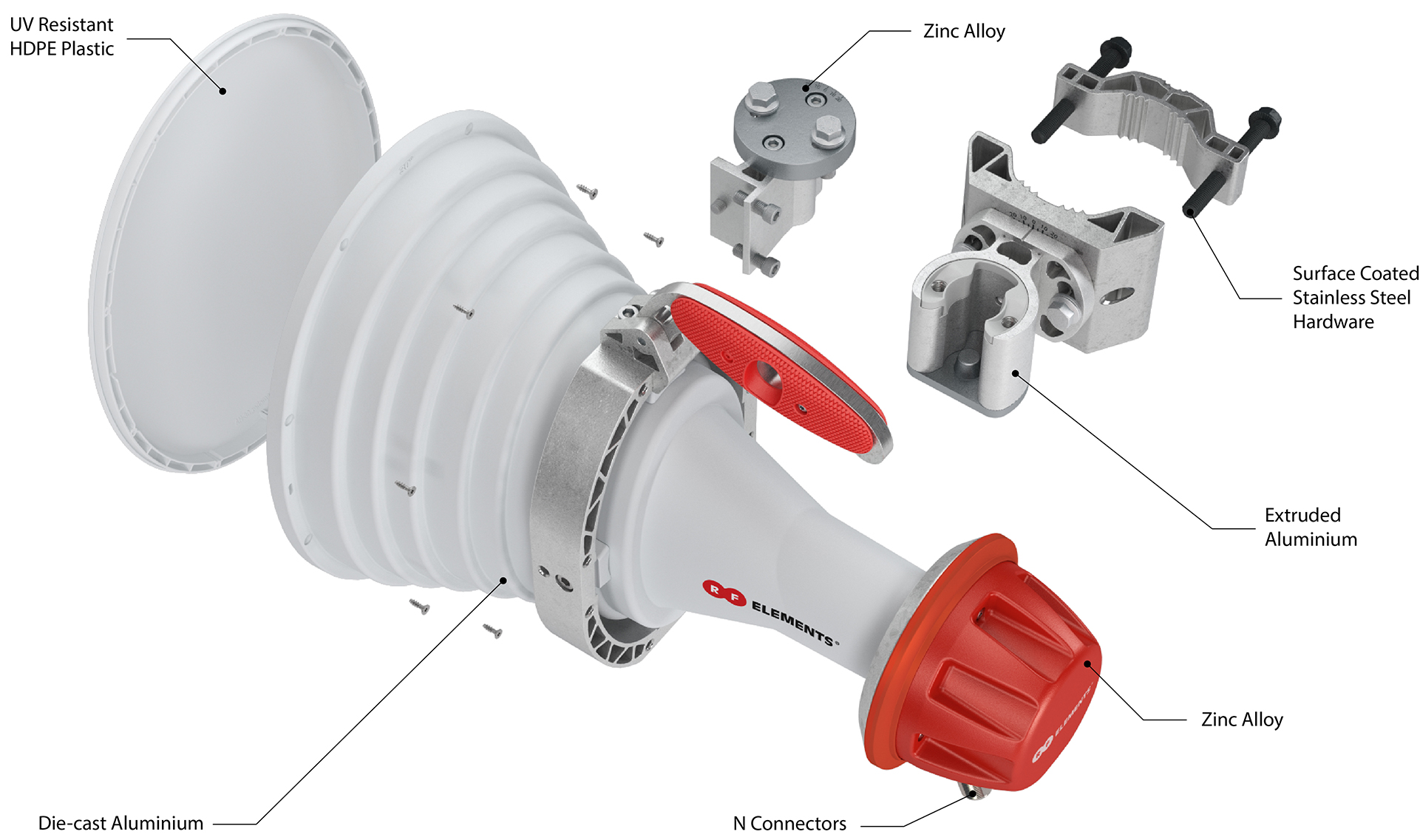
Asymmetrical Horn CC Antennas have solid aluminium body, built to last and resist any weather conditions. We use the most suitable materials: die cast, stamped, and extruded aluminium; stainless steel, high quality ABS plastic, and high density polyethylene.
Innovative Bracket
Asymmetrical Horn CC Antennas feature an innovative mounting system. The mount is separated from the antenna, making the installation and adjustment quick and easy.
Step 1: Bracket Installation
First install the bracket on the pole. The pole bracket is reversible: it can be mounted on the left or the right side of the antenna.
Step 2: Antenna Adjustment
Simply slide the antenna in the bracket and adjust the elevation and the azimuth. Tighten the screws to finish the installation. Only one tool is needed for the entire installation.
Specification
| AH60-CC | |
| Radio Connection | 2x N Female Bulkhead Connector |
| Antenna Type | Horn |
| Materials |
UV Resistant ABS Plastic Polycarbonate Aluminium Stainless Steel |
| Enviromental | IP55 |
| Pole Mounting Diameter |
40-80 mm (1.5-3.1 inch) Recommended as close to 80 mm (3.1 inch) as possible |
| Temperature | -35°C to +60°C (-31°F to +140°F) |
| Wind Survival | 160 km/h (100 mi/h) |
| Wind Load | 48/85 N - Front/Side at 160 km/h (100 mi/h) |
| Mechanical Adjustment | ± 20° Elevation, ± 20° Azimuth |
| Weight | 4.6 kg (10.0 lbs) |
| Dimensions |
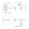
Width (with bracket): 315 mm Height: 334 mm Length: 494 mm |
| Performance | |
|---|---|
| Frequency Range | 5180 - 6000 MHz |
| Gain | 17 dBi |
| Azimuth Beam Width -3 dB | H 45° / V 42° |
| Elevation Beam Width -3 dB | H 17° / V 16° |
| Azimuth Beam Width -6 dB | H 60° / V 60° |
| Elevation Beam Width -6 dB | H 25° / V 25° |
| Beam Efficiency | 95% |
| Front-to-Back Ratio | 27 dB |
| VSWR Max 5180-6000 MHz | 1.8 |
| Polarization |
Dual Linear H + V |
| Impedance | 50 Ohm |


 Polski
 English
 Italiano
 Español
 Čeština
 Српски
 Deutsch
 Ελληνικά
 Slovenský

